Receiving METEOR M2-4 Weather Satellite Images with an RTL-SDR and a Homemade Yagi Antenna
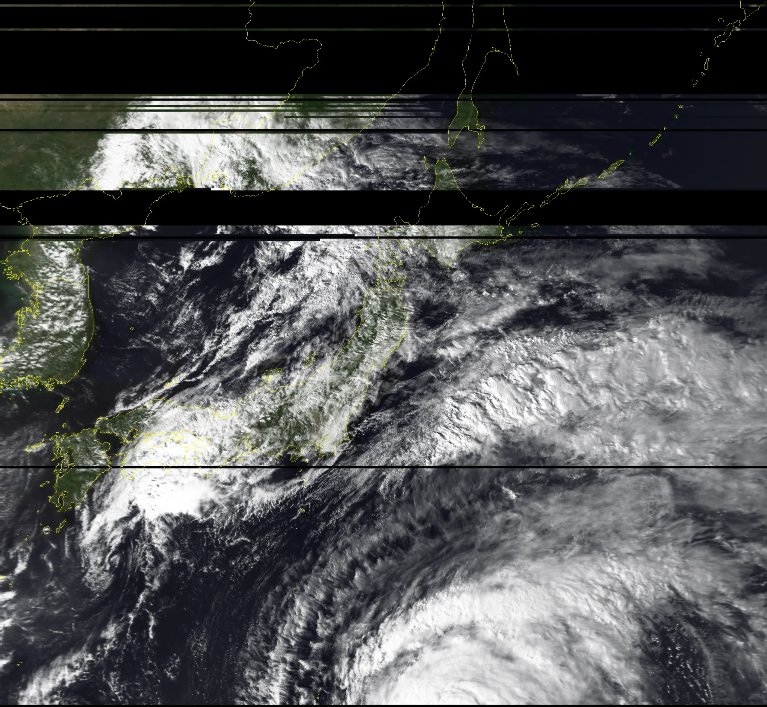
Table of Contents
Background
I’ve been playing way too much Genshin Impact lately, and now I’m worried that the sky in this world might be fake too. How would I prove there’s no giant artificial dome over our heads?
Detecting the Schumann resonance
If there were a dome, we wouldn’t be able to detect the natural Schumann resonance at around 8 Hz. Instead, we’d detect a much higher resonance whose frequency depends on the size of the dome.
But an antenna that resonates at 10 Hz would be absolutely gigantic, so this seems pretty hard to pull off as an individual.
Detecting the hydrogen line
If there were a dome, the stars would be fakes projected onto it, too. Even if a real universe and its hydrogen line existed outside the dome, the dome would block them. In other words, if I can detect the hydrogen line, I can prove there’s no dome in the sky.
But the signal is apparently extremely faint, so it would take extra equipment and processing. And even if I did detect it, there’s no information riding on it, so it’s a bit lacking in fun.
Receiving signals from a satellite
If there were a dome, radio waves from space would be blocked by it. In other words, if I can receive signals from a satellite, I can prove there’s no dome in the sky. It’s possible that the administrators of this world have placed artificial satellite signals on the dome, but let’s ignore that.
Luckily, satellite communications use frequencies around 135 MHz. The neighborhood has amateur radio bands and the airband, so if I make an antenna that can receive around these frequencies, it’ll be versatile enough to be useful for other things too. Nice.
So, let’s receive satellite images from METEOR M2-4 with a homemade Yagi antenna!
Choosing and Designing the Antenna
The target is the Russian weather satellite “METEOR M2-4”, which is still in operation. Its frequencies are 137.100 MHz / 137.900 MHz (VHF band, wavelength of about 2.18 m).
To pick up faint signals from space in the awful radio environment of central Tokyo, I might need some directivity. So I decided to build a 3-element Yagi-Uda antenna myself.
Main materials
Consulting with Professor Gemini (the AI), I put the whole thing together from stuff lying around the house and 100-yen-shop materials.
The materials are as follows.
- Frame: four plastic pipes, roughly 70 cm x 5 mm
- I happened to find them at the garbage collection point. They were probably morning glory support stakes from somebody’s summer vacation science project.
- Without them, I would have had to go buy PVC pipes. Super lucky.
- Elements: a 5 m metal tape measure from Daiso (a Japanese 100-yen shop)
- That’s right, I’m building a so-called tape measure dipole antenna.
- Feed point: copper foil tape + coaxial cable + heat-shrink tubing
- For the coax, I used 75 Ω cable that I bought in Akihabara (Tokyo’s electronics district) for 100 yen per 10 m (about $0.65)(!). Of course there’s the impedance mismatch, but I figured an SWR of 1.5 is fine for receive-only use.
Design dimensions
Using a Yagi-Uda antenna calculator I found online, I got the following dimensions.
[Design dimensions (based on 137.0 MHz / converted for an effective element diameter of 15 mm)]
[ Director ] : approx. 97.9 cm │ spacing 34 cm[ Driven element ] : approx. 104.7 cm (51.9 cm on each side + 1 cm gap) │ spacing 34 cm[ Reflector ] : approx. 109.3 cmBuilding the Half-Wave Dipole Antenna
The basic structure of a Yagi-Uda antenna is a single driven element, sandwiched between a reflector and a director. The driven element is simply a half-wave dipole antenna, so let’s build that first.
I’d been struggling to find a good way to attach the feed point, but when I searched around, I found a genius method: cut an extra piece of tape measure, insulate it, sandwich the left and right elements with it, and fix everything in place with heat-shrink tubing.
With this, you need no extra materials or space. On top of that, it doesn’t ruin the U-shaped cross-section that the tape measure needs to stay stiff. It’s also waterproof, and easy to store. Truly genius.
Attaching a connector to the end of the coax
I forcibly attached an SMA connector (female) from Akizuki Denshi (a well-known electronics parts shop in Akihabara). 30 yen each.

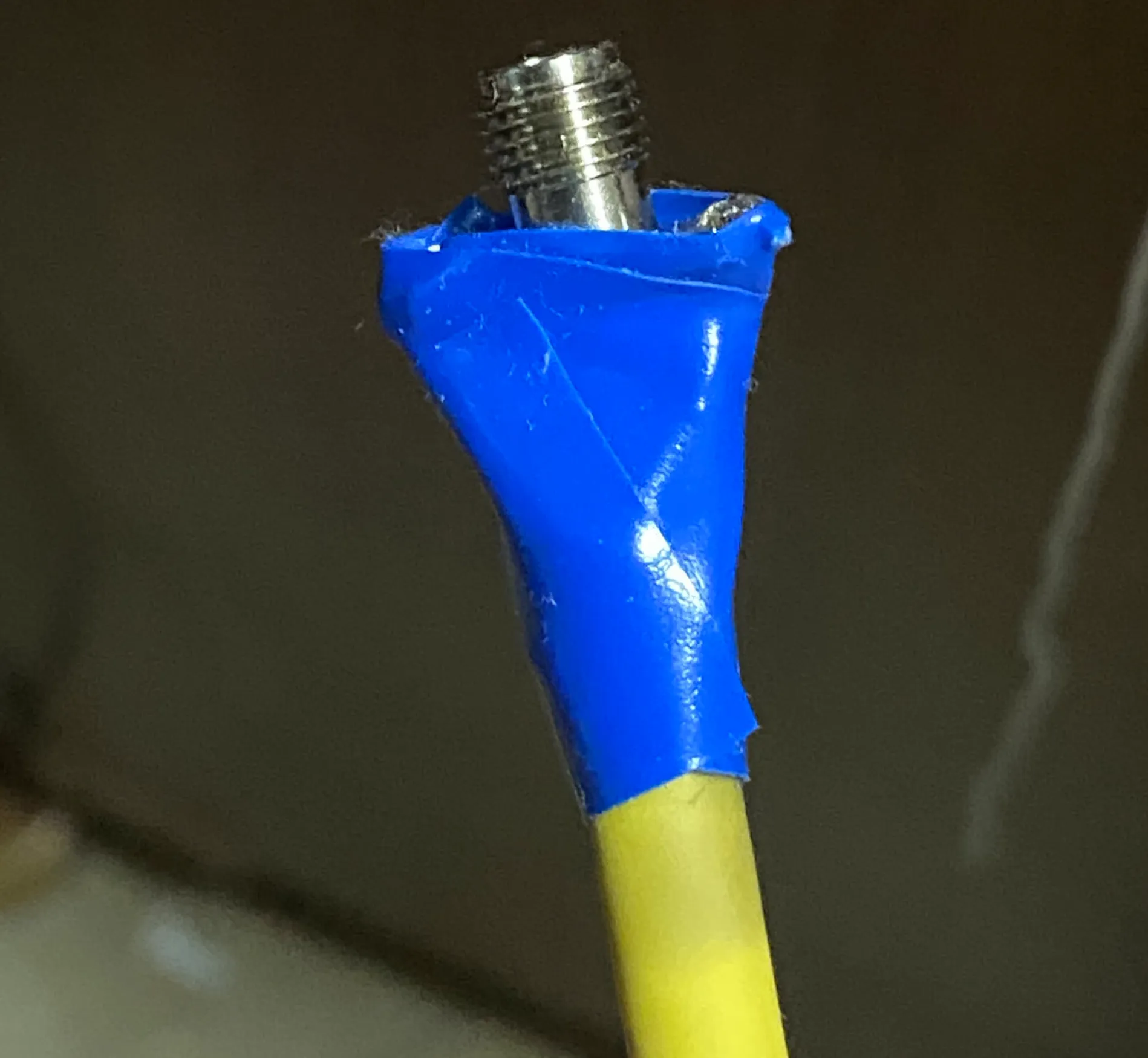
I stripped the coax, wound the center conductor into a coil around the connector’s center pin, and soldered it. Then I twisted the shield into two strands, passed them through the hole in the connector, and soldered those. Finally, I protected the whole thing with insulating tape and heat-shrink tubing, and that was it.
This was actually the end termination of a magnetic loop antenna (MLA). The MLA itself got finished, but the results were meh, so I cut it partway and reused the cable.
Making the tape measure half-wave dipole
Next, let’s make the half-wave dipole out of tape measure.
Apparently, turning it into a Yagi slightly shifts the resonant frequency. So I made it to exactly the dimensions from the antenna calculator above. Note that these differ slightly from a plain 137 MHz half-wave dipole.
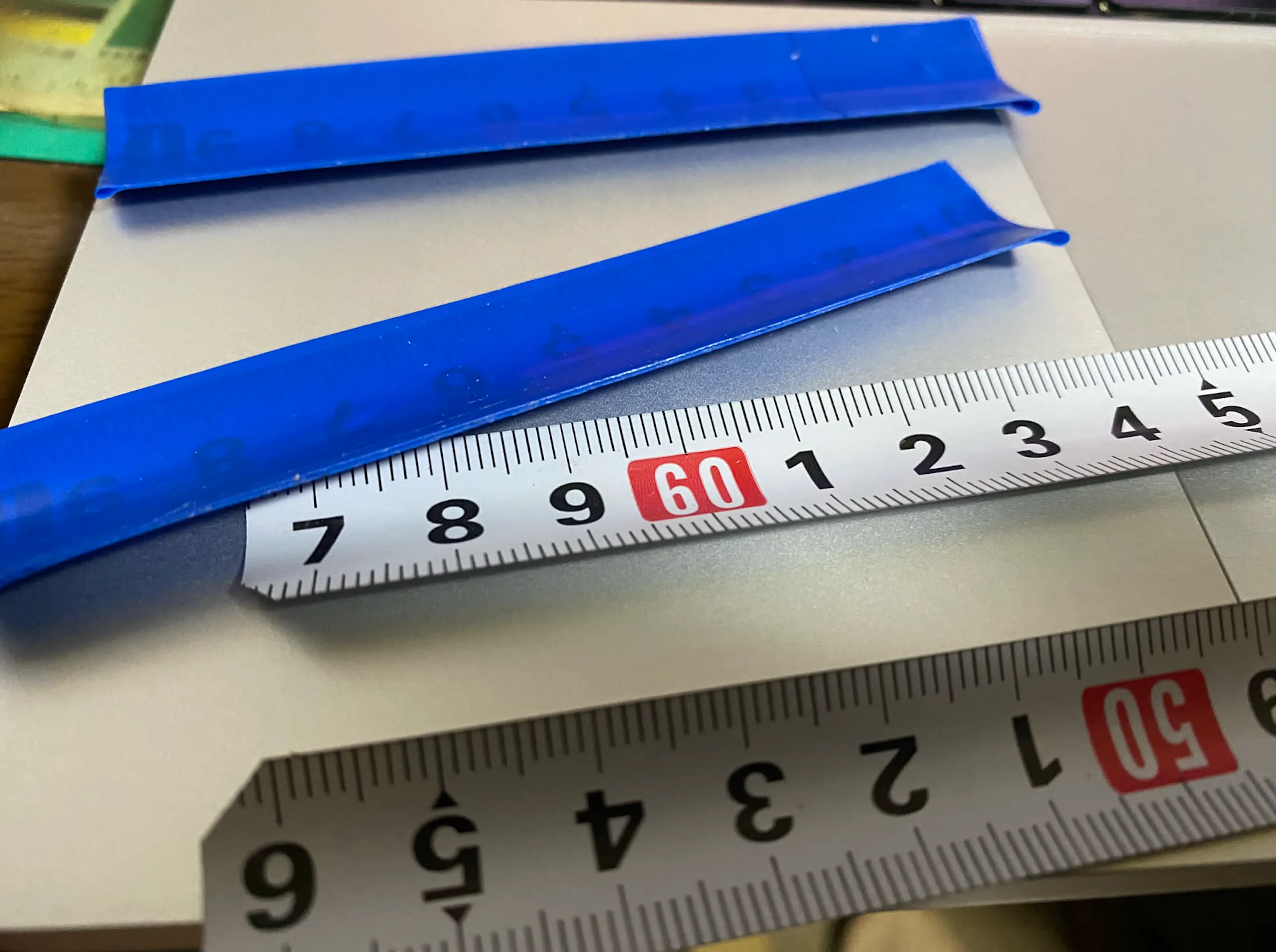
Take a 100-yen-shop tape measure and cut it according to the design dimensions above. Also cut two 10 cm pieces to protect the feed point. Cutting steel with regular scissors seriously wears them down, so you probably shouldn’t use your favorite pair.
The cut ends are very sharp, so round off all the corners. The 10 cm pieces for protecting the feed point are completely covered with insulating tape.
I scrubbed the feed point with sandpaper to strip off the tape measure’s paint and expose the bare metal. Then I stuck copper foil tape on top so the solder would take better. The copper foil tape might not be necessary, but I’d recently bought some and was blown away by how well solder sticks to it, so I took the chance to use it.
I stripped 15 mm of the outer jacket from the end of the coax, then bundled the shield into one strand and folded it back. I stripped 10 mm of the inner insulator to expose the center conductor. It was easiest to first position the center conductor so it connects almost straight to one element and solder it, then solder the shield to the other element. The distance between the elements was about 8 mm.
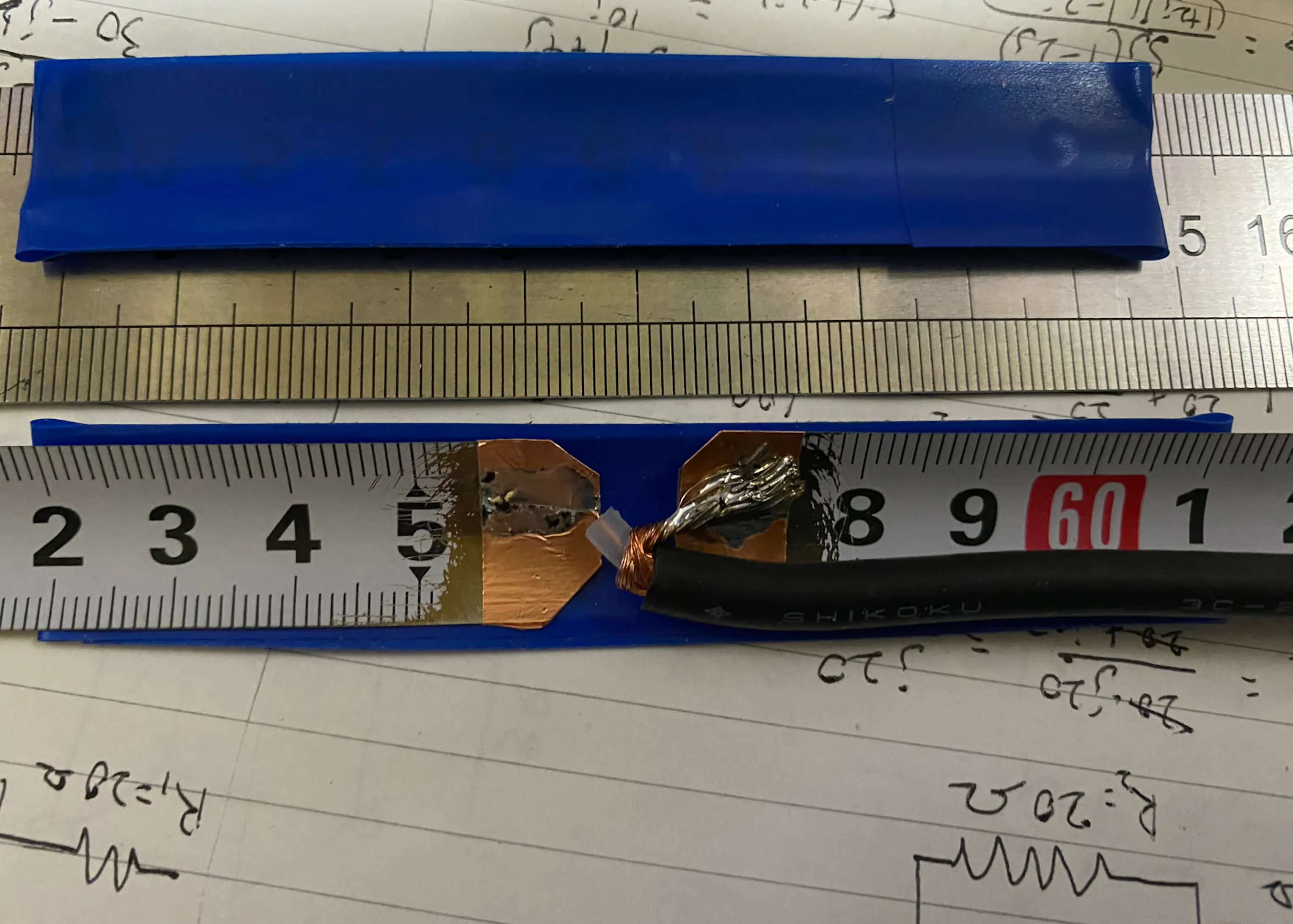
I covered the dead center of the feed point with insulating tape, then slid heat-shrink tubing over it and heated it to fix it in place. The coax comes out of the element on the shield side.
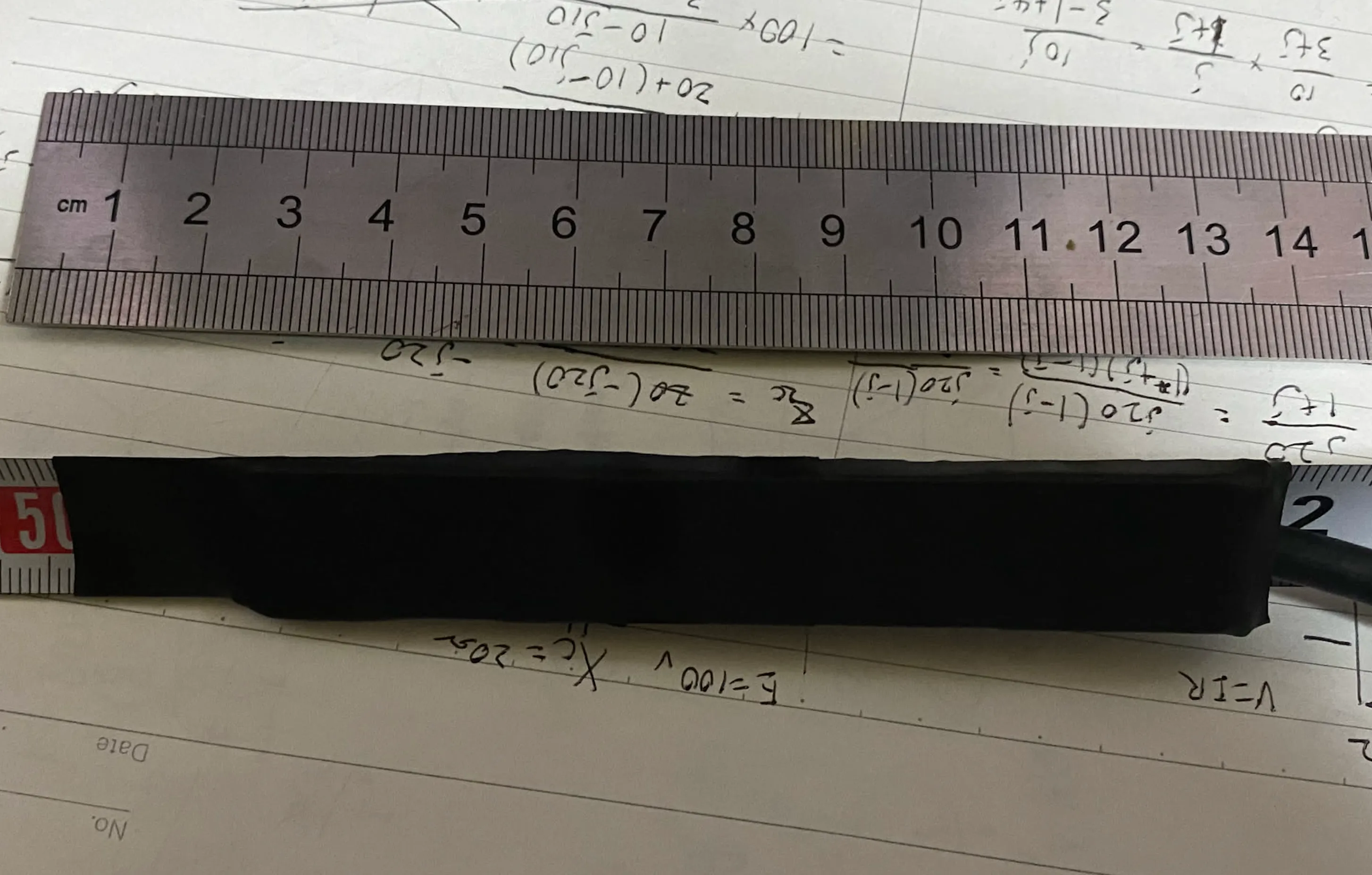
Measuring the single dipole with a NanoVNA
Now that the feed point is done, let’s use a NanoVNA to check whether this single dipole resonates at the frequency I was aiming for.
I measured S11 with the antenna held away from any metal and the floor, and got the following results.
- Marker: 137.500 MHz
- SWR: 1.555
- Impedance: 50.96 + j22.43 Ω
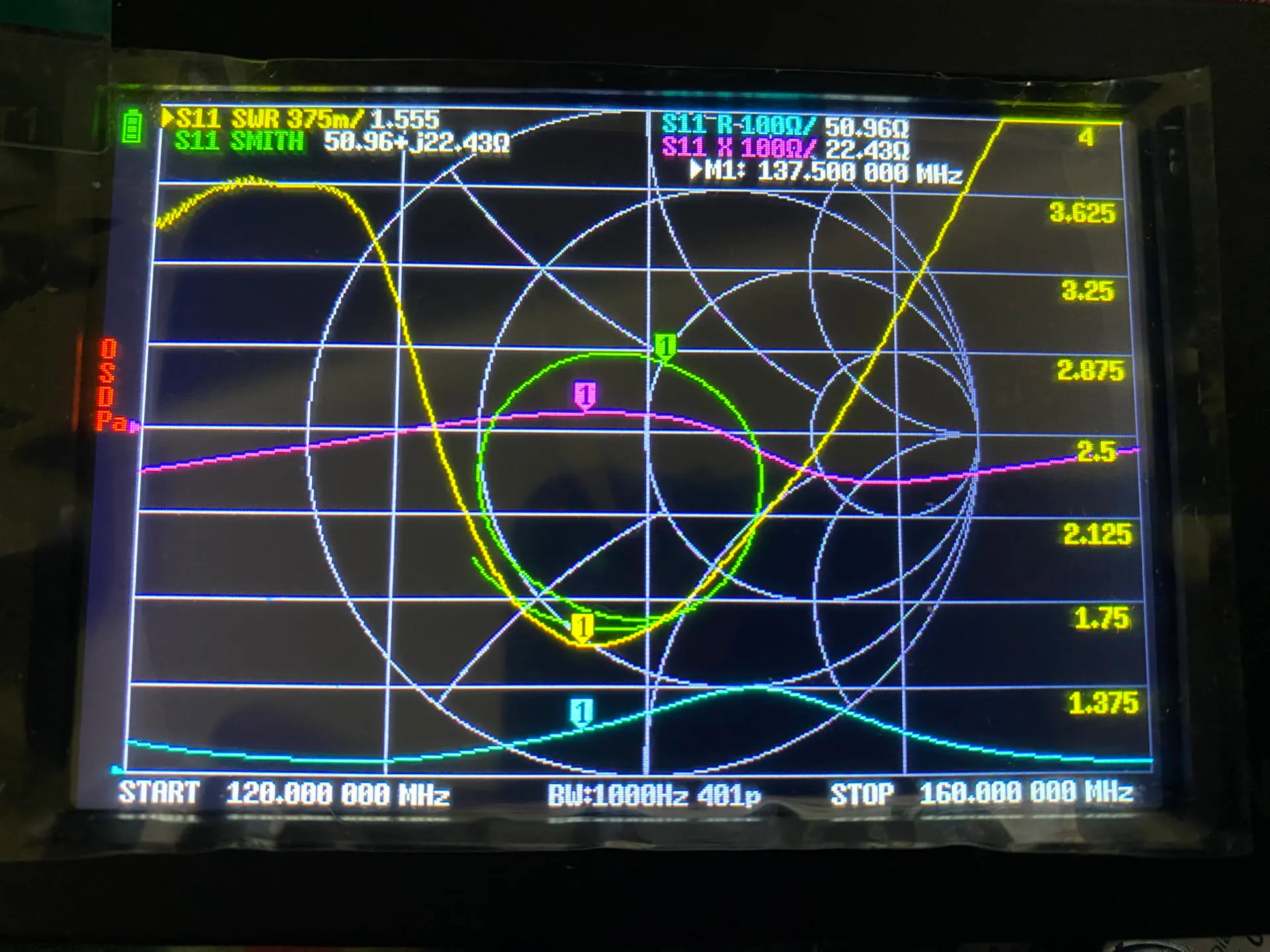
I was a little worried about whether an SWR of 1.5 is okay, but apparently once it becomes a Yagi, the mutual coupling with the director and reflector shifts the resonant frequency. So I didn’t trim the elements yet and just built it into the Yagi frame as it was.
Building the 3-Element Yagi Antenna
Now that the driven element is confirmed working, I’ll attach the reflector and the director to extend it into a 3-element Yagi antenna.
I wrapped tape around both ends of two morning glory poles to give them strength. By the dimensions, the driven element and reflector should sit right at the ends, so this was also meant to make friction hold them firmly in place.
At the positions of the driven element, reflector, and director, I tied two zip ties spaced slightly narrower than the width of the tape measure (a bit under 16 mm). These act as rails: they stop the tape measure from sliding back and forth, and they keep the U-shaped cross-section, which the tape measure needs for its stiffness, from collapsing even when I tie things down tightly afterward.
I placed the cut tape measure pieces on these rails and fixed them by tying zip ties in an X pattern. I put them with the valley of the tape measure facing the frame.
I did this for the driven element, the reflector, and the director, and the Yagi antenna was done.
(Also, having no place at all to hold it by hand turned out to be way too inconvenient, so I later taped two more poles on to make a handle. The handle is about 50 cm, and the reflector-to-director length is 70 cm.)
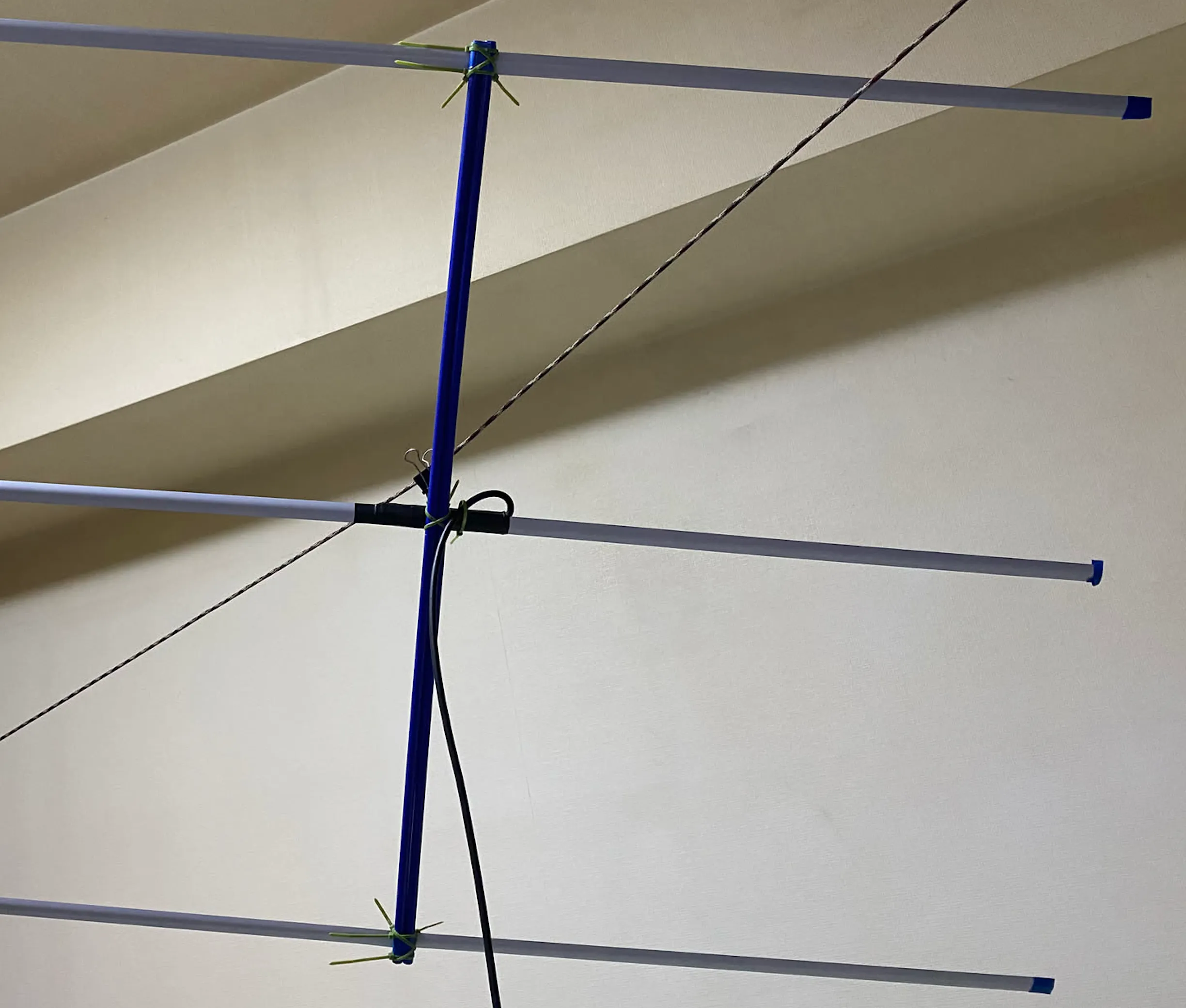
In this state, I connected the NanoVNA again and fine-tuned the position of the director back and forth by a few millimeters.
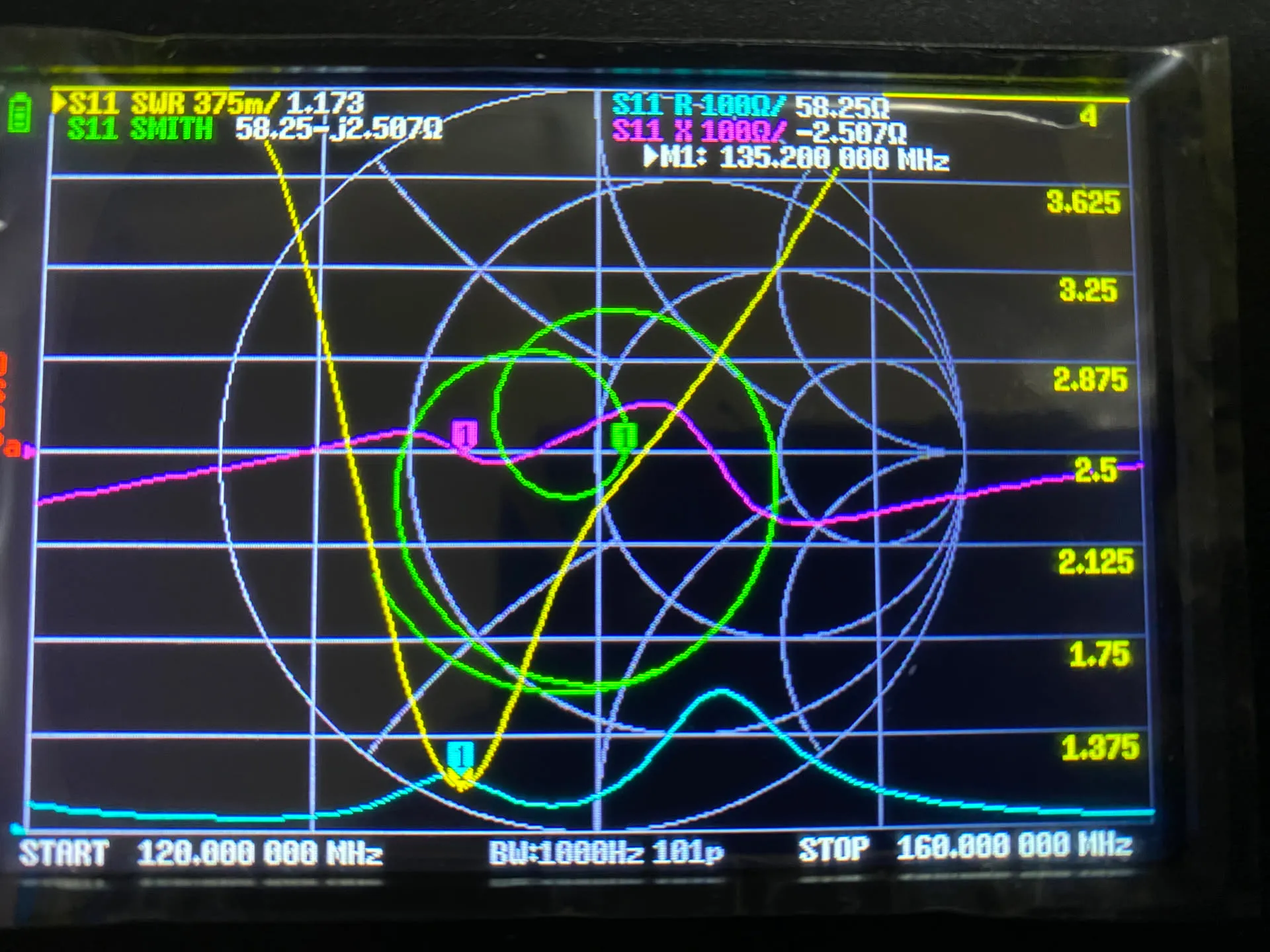
- Peak: 135.200 MHz, SWR 1.173 (Z = 58.3 - j2.5 Ω)
- Target: 137.200 MHz, SWR 1.566 (Z = 32.6 - j5.6 Ω)
At the bottom of the dip, it hit an SWR of 1.17, a seriously surprising match. Even around 137.9 MHz, where it counts, the SWR stays in the 1.5 range, which works out to more than 95% of the received power going straight into the SDR.
(But the coax is 75 Ω, so a perfect match at 50 Ω was meaningless in the first place…)
I considered trimming the elements further for fine-tuning, but it was already good enough, I didn’t want to risk causing a catastrophe by messing with it any more, and I didn’t want to beat up my scissors any further, so I called it done.
The total build cost was about 300 yen.
A Midnight Test Run and the “Canyon Between Buildings” Wall
I got the idea at 5 PM on a Sunday and bought the tape measure, and the antenna was finished at 3 AM. I immediately went out on the balcony and fired up SDR++, but it was eerily quiet. I thought it was broken, but come to think of it, there are no domestic flights at 3 AM.
After waiting a few dozen minutes while watching Flightradar24, I found an international cargo flight over the Pacific off Choshi in Chiba Prefecture. I listened in on Tokyo Control (Kanto East sector, 133.600 MHz AM) and… I could faintly hear a pilot talking in English!
A bundle of tape measure had really picked up radio waves from the sky!
Receiving Signals from METEOR-M2
All that’s left is to put this antenna into actual operation. Extremely luckily, it turned out that the Russian weather satellite METEOR M2-4 would pass over Tokyo on October 5 (Monday), from 13:47 to 14:02, with a maximum elevation of 73 degrees.
It’s a perfect, almost-directly-overhead pass, but the sky is far too narrow from the balcony of my room, which sits at the bottom of a canyon of buildings.
So I decided to use “the landing of the emergency stairs leading up to the roof of my apartment building.” From here, I’d be at over 30 m above sea level, rising up to almost the same height as the roofs of the surrounding buildings.
Preparation
First, I got an iOS app for tracking satellites. The App Store had several similar apps, but I went with “Satellite Chaser” because it’s free, can track METEOR-M2, and has an AR feature. There might be better ones, but it was already about T-minus 1 hour at that point, so I was in no position to be picky.
Next, I got SDR++ set up. Until now I’d only used it to listen to FM and SSB, so I struggled a bit, but the following settings were needed (summary by Professor Gemini).
- Setting up to wait for both signals at once (super important)
- Center Frequency:
137.500 MHz - Sample Rate:
1.024 MSPS - Depending on the day, Meteor-M2 4 transmits on either “137.100 MHz” or “137.900 MHz”. If you set the sample rate to 1.024 MSPS and center it on 137.500 MHz, right in the middle, the entire band from 137.0 MHz to 138.0 MHz fits on the screen. That way, whichever frequency the signal comes in on, you won’t miss it, 100%.
- Center Frequency:
- Gain settings
- RF Gain: around
32 to 36 dB - The noise floor is high in a city during the day. Setting the gain to maximum causes internal saturation that crushes faint signals, so the trick is apparently to deliberately back it off a little.
- RF Gain: around
- Recording module
- Open “Recorder” in the menu and always set Record Mode to “Baseband (raw IQ recording)”. (Note: if you pick “Audio”, everything outside the audio band gets chopped off and the image data is dead, so absolutely NOT that.)
- Set the format to
WAV (Int16). Set the save location to the desktop and you’re ready to go.
Operation Arcadia
Carrying a laptop, the RTL-SDR, my homemade Yagi antenna, a camping chair to put the laptop on, and a towel in case it started raining, I headed to the top of the emergency stairs and hurried to get set up. Almost the moment I finished, the satellite rose over the horizon on my iPhone’s AR screen.
Holding up the antenna and trusting the AR display, I watched a bump gradually appear around 137.9 MHz on the waterfall. It was the signal from the satellite!
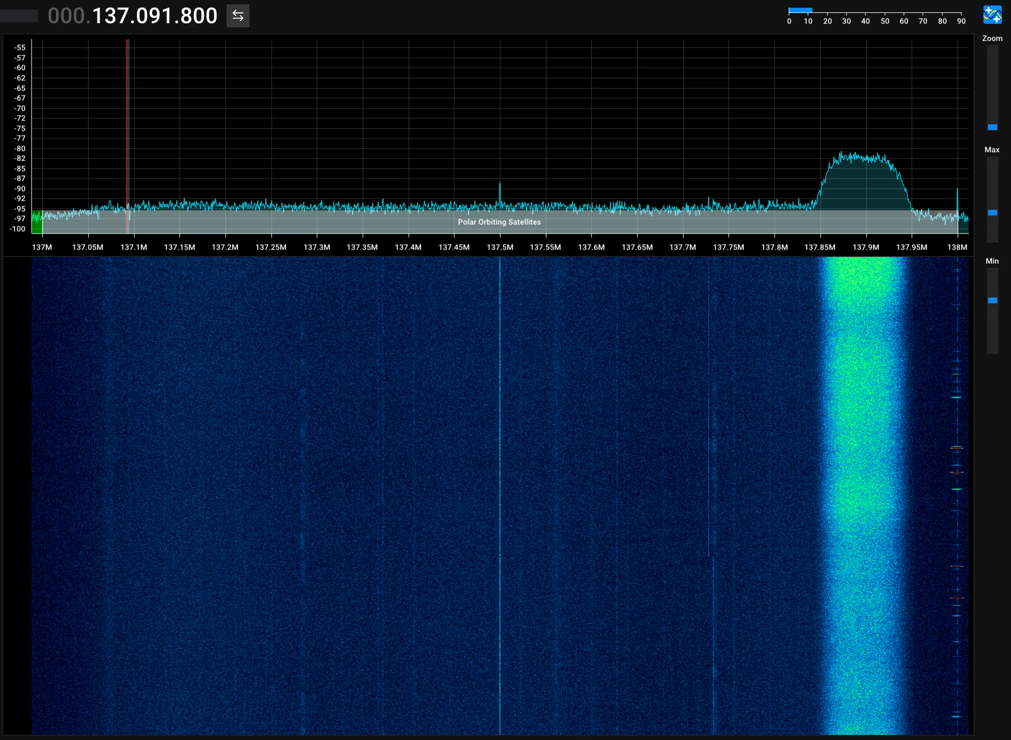
After that, for the 15 minutes until the satellite set, I just kept chasing it, phone in my right hand, antenna in my left. At one point along the way, the laptop went to sleep. I should have turned that off in the settings.
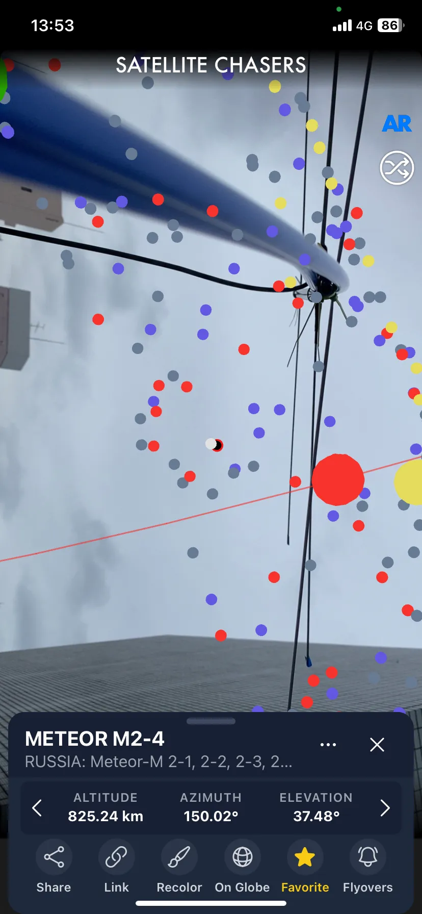
As expected, the signal strength peaked around when the satellite reached the zenith, then gradually weakened, and when it sank below the horizon, the signal vanished completely. Yep, this is definitely the real deal!
Decoding
I went back to my room carrying the huge recorded WAV file (about 2.7 GB). In the elevator, another resident got on and it got a bit awkward. Maybe I should have properly stowed the antenna before getting in.
Now it’s time to restore (develop) the image. For decoding, I used SatDump (v1.2.2), open-source satellite processing software.
I figured the image would show up right away, but the parameter settings, typical of digital communications, were far more finicky than I expected. Just mashing buttons at random gets you nothing.
After a lot of trial and error, here are the settings that finally produced an image.
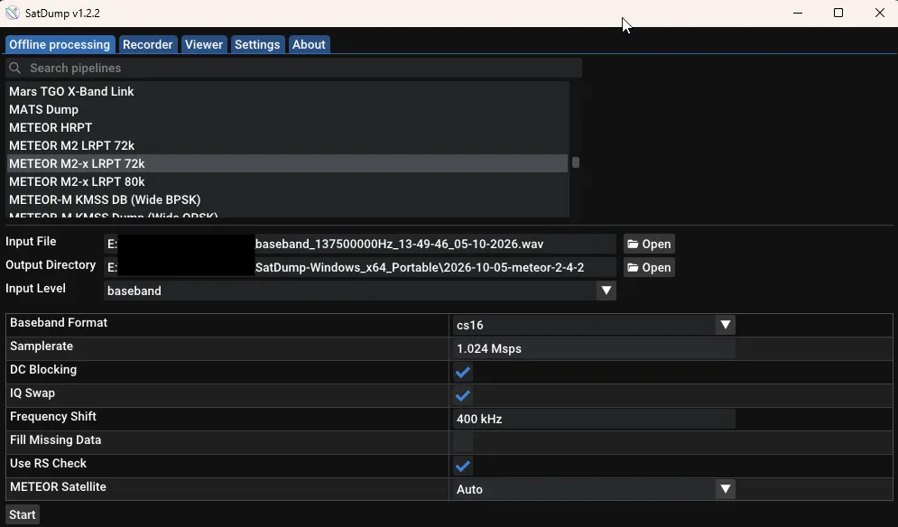
They look like a screen full of magic spells, but each parameter has an important physical or mathematical meaning.
What each setting parameter actually means
Summary by Gemini again.
- Pipeline:
METEOR M2-x LRPT 72k- Meaning: selecting the demodulation pipeline
- It’s “72k”, not “80k”. It’s also important to pick “M2-x”, which supports the newer satellites, rather than the older-generation “METEOR M2”.
- Input File:
...baseband_137500000Hz_13-49-46_05-10-2026.wav- Meaning: the raw recorded data file
- You can tell at a glance from the file name. It’s a raw log of “center frequency 137.5 MHz, started at 13:49:46 on October 5, 2026”. The timestamp of the desperate scramble up the stairs to get set up is preserved right there.
- Input Level & Baseband Format:
baseband/cs16- Meaning: specifying the raw waveform data and its quantization format
- Select
baseband, the raw IQ waveform, and specifycs16(Complex Signed 16-bit), which is what SDR++ recorded.
- Samplerate:
1.024 Msps- Meaning: declaring the sample rate
- Specify the same “1,024,000 samples per second” as when recording. If this doesn’t match, time runs at the wrong rate and the modulation frequency won’t line up.
- DC Blocking:
checked (ON)- Meaning: removing DC offset noise
- Direct-conversion receivers like the RTL-SDR inevitably produce an “unwanted DC spike (DC offset)” sticking up right in the middle of the center frequency (137.500 MHz). Checking this cancels it out in software.
- IQ Swap:
checked (ON)(super important)- Meaning: swapping the complex signal’s I and Q components
- If the real (I) and imaginary (Q) axes are reversed, the “plus and minus” of the frequency get mirror-flipped. When you’ve set the offset correctly but still can’t demodulate, checking IQ Swap usually fixes it like magic. A hidden trap of digital radio. This was what took me the longest to figure out.
- Frequency Shift:
400 kHz- Meaning: correcting the offset from the center frequency
- Since I recorded centered on 137.500 MHz, the target 137.900 MHz is “+400 kHz” to the right. If you leave this at
0 Hz, it searches an empty lot with nothing in it and errors out instantly. Specify exactly400 kHzto snipe the signal bump.
- Use RS Check:
checked (ON)- Meaning: error correction with Reed-Solomon codes
- The guardian angel of space communications. Using the error-correcting code (Reed-Solomon) carried in the packets, it mathematically repairs bits that got garbled by noise during reception. Thanks to this, the image stays connected without falling apart even when the signal is somewhat weak.
- Fill Missing Data:
unchecked (OFF)- Meaning: whether to interpolate missing data
- Apparently, checking it fills in rows with missing data in some plausible way, but this time I deliberately left it OFF.
Result
After setting all that up and running it, the constellation on the screen snapped into four crisp points forming a neat square. Wait, so THIS is that mysterious diagram that shows up in the Second-Class Radio Operator exam (Japan’s radio engineer license)!
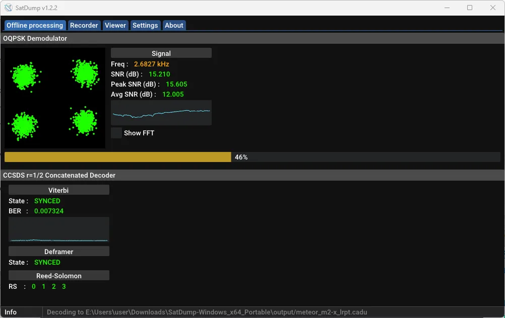
When processing finished, I opened the output folder and this was waiting for me.
It actually came out upside down, so I rotated it 180 degrees. The satellite scans along its direction of travel, so when it flies from south to north, the picture gets scanned starting from the south of the Japanese archipelago and moving north, which means that on a map with north up, it naturally ends up upside down. At least, that’s what I’m told.
There’s some missing data, but I got almost a perfect image. The three-dimensional feel of the clouds is amazing. The thing cut off at the bottom of the image is Typhoon No. 27.
This is a raw photo of the Earth, possibly the only one of its kind in the world(?), captured directly with an antenna I built myself and an RTL-SDR, from radio waves transmitted from space 820 km up. I never expected it to go this well, so I couldn’t help but yell out loud.
Conclusion
There is no false sky above Tokyo, and outer space and weather satellites are real. Even if there were a false sky, the administrators of this world must be doing something pretty elaborate.

More articles
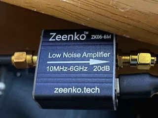
- I Bought a Cheap Wideband LNA from AliExpress, the Zeenko ZK06-BM• #RadioI used the Zeenko ZK06-BM to intercept METEOR-M2 4 and got the best satellite image I've ever received.
- NOAA-15, 18 and 19 Are Out of Service, and the 137 MHz Analog Weather Satellites Are Gone• #RadioElon Musk is a cancer on humanity.

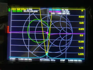
- Building a Homemade Preselector to Improve RTL-SDR Reception• #RadioI've finally started doing some actual radio-engineering electronics projects.
- Getting Started with SDR Using an RTL-SDR Blog V4 and a Random Wire Antenna• #RadioA record of trying shortwave listening with a stealthy random wire antenna dangling off my balcony, from setting up the RTL-SDR Blog V4 to the before-and-after sensitivity gains of a homemade 9:1 unun.


Notes on games, radio and technology, translated from the Japanese blog.