Building a Homemade Preselector to Improve RTL-SDR Reception
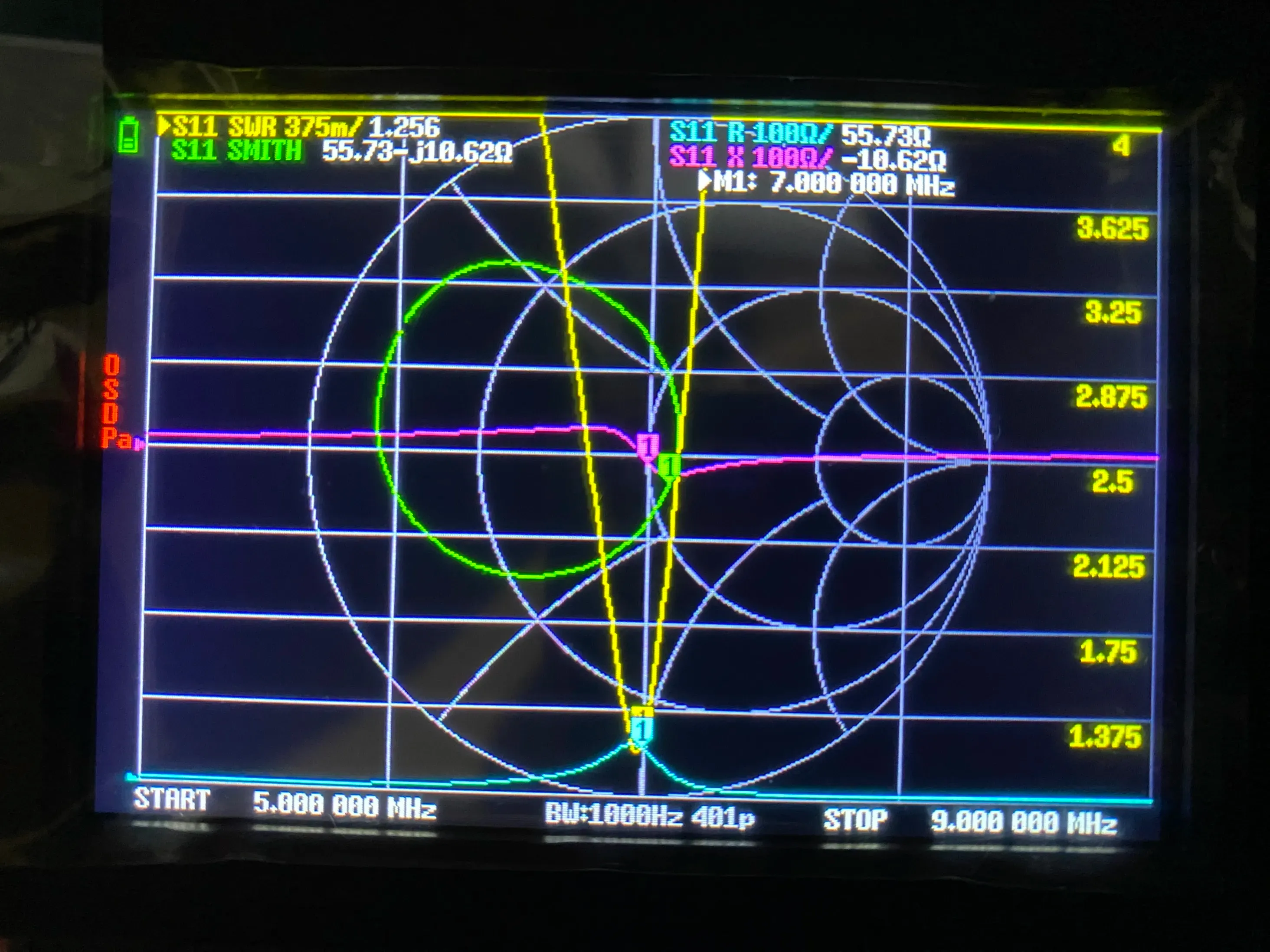
Table of Contents
Lately my interest in radio as a hobby has come roaring back for no particular reason.
Going back and studying radio engineering from the basics, I keep getting that satisfying puzzle-pieces-clicking-into-place feeling: “Ohh, so THAT’s why it works that way!”
Once you understand the theory, you want to put it into practice. This time I threw everything I’d learned at the problem and went for a serious upgrade of my home SDR (software-defined radio) receiving setup.
Previous article:
Getting Started with SDR Using an RTL-SDR Blog V4 and a Random Wire Antenna
Motivation
Especially on the 40m band (the amateur radio band around 7MHz), if I set the RTL-SDR’s RF gain to 20dB or more, a ton of mysterious ghost signals pop up all over the band. It seems that powerful AM broadcasts from China, on nearby frequencies, are somehow leaking into frequencies they have no business being on.
When I looked into it, this turned out to be a phenomenon called third-order intermodulation distortion. When a strong signal is landing right next to the band you want and you crank the RF gain too high, the mixer and amplifier clip because of their nonlinearity. As a result, fake signals that shouldn’t exist at all get generated at positions like
And since there are multiple strong Chinese shortwave broadcasters, these intermodulation products multiply like crazy too.
The RTL-SDR can receive a wide range of frequencies, but the flip side is that its input stage is almost completely defenseless. As far as I could tell, the fix is to physically knock down the strong out-of-band signals before they reach the receiver, and a “preselector”, which is basically a bandpass filter, is supposed to help a lot with that.
Building a Transformer-Coupled Parallel-Resonant Preselector
I built a passive preselector using a parallel resonant circuit.
Circuit Configuration and Parts Selection
The basis is a tank circuit with an inductor () and a variable capacitor () connected in parallel. A parallel resonant circuit has maximum impedance (theoretically infinite) at its resonant frequency. Place it properly in the signal path so that only the band you want passes through with low loss, and everything off-frequency (especially the powerful medium-wave and shortwave broadcast bands) gets knocked way down. Apparently.
Consulting Professor Gemini (the AI) along the way, I decided to build the following circuit (no confidence that it’s correct).
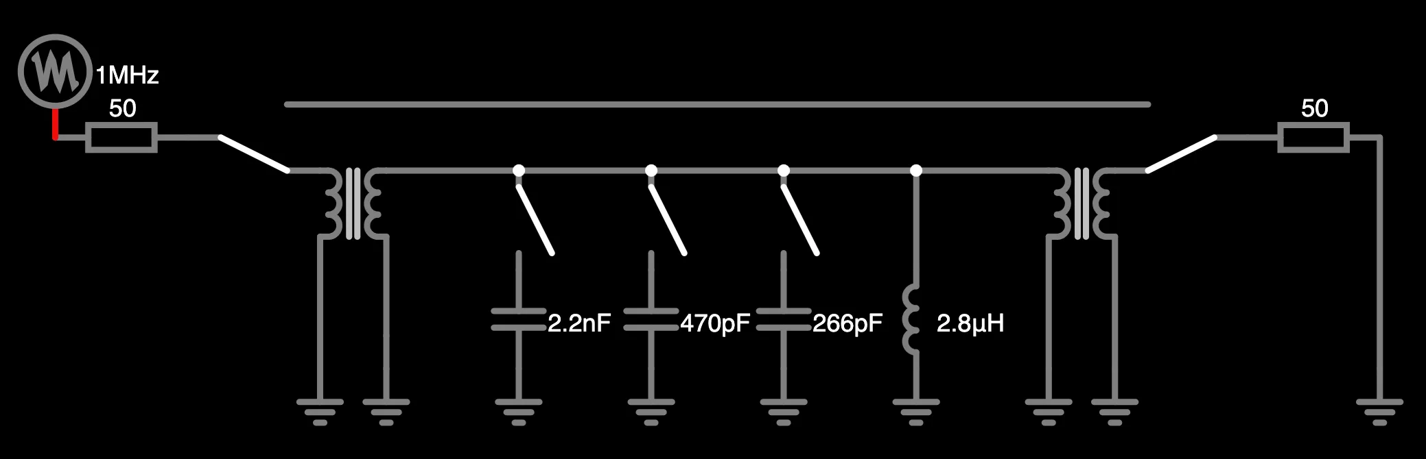
The 266pF capacitor in the diagram is actually a variable capacitor, adjustable from 5pF to 266pF.
Also, the diagram shows five coils, but in reality they are all wound on a single toroid core. For the core I used a T68-2 (red), which is handy across a wide range of the HF band. Apparently 22 turns of 0.4mm enameled copper wire (UEW) gives 2.8uH. The input and output windings each get 3 turns.
An Intuitive Way to Think About It
A resonant tank is like a swing.
The person pushing the swing is the input, and the person on the other side who gets kicked by the swing is the output. If you push at a frequency that matches the swing’s natural frequency, the swing goes higher and higher, and the kick it delivers gets stronger. Pushes at any other frequency can’t be transferred efficiently through the swing, so they barely show up on the output side.
In other words, it’s a bandpass filter (BPF).
Changing a swing’s natural frequency is hard, but with a resonant tank circuit you can tune the resonant frequency fairly freely by changing the total capacitance. Add a big capacitor in parallel to roughly set the resonant frequency, then fine-tune with the variable capacitor, and you can make it resonate at pretty much any frequency you like. That’s the idea.
Another key point is that the resonant tank is connected through a transformer. In swing terms: if a grown adult grabs the swing firmly with both hands, the precious swinging (the resonance) stops right away (this is the state where impedance isn’t matched).
So we use a transformer, and with the 3:22 turns ratio we “give the swing a light poke with a fingertip, and receive the motion on the other side with just a fingertip touch.” This way, the signal can be handed over efficiently while keeping the swing’s sharp natural oscillation (a high Q, i.e. a filter with a crisp, sharp response).
By the way, this design apparently has a bunch of other benefits too. From a DC point of view, the antenna is completely shorted to ground through the transformer coil, so static electricity can’t build up. There are cases where, when you plug or unplug an RTL-SDR, static built up on the antenna zaps through and kills it, and this avoids that. This circuit also effectively works as an antenna coupler, so it should be easier to match impedance with random wire antennas, which tend to be high impedance.
Calculating the Theoretical Coverage
With and a variable capacitor of , adding fixed capacitors (, ) with switches lets you cover the main HF bands broadly, as follows.
Resonant frequency formula:
- Variable capacitor only () about (from 7MHz on the 40m band up through the 20m/15m/10m bands)
- Variable capacitor + () about (right on the 3.5MHz area of the 80m band)
- Variable capacitor + () about (covers the 1.9MHz area of the 160m band)
Depending on the on/off combination of the switches, the main amateur radio bands should be nearly continuously covered. Incidentally, I had Professor Gemini do all of these calculations.
Construction
I bought the electronic parts in Akihabara (Tokyo’s famous electronics district). For the enclosure I repurposed a plastic case meant for an ESP32 board, and assembled the preselector with the toroid core and variable capacitor inside. The variable capacitor was the most expensive part, but the total cost came in under 1,000 yen (about $7).
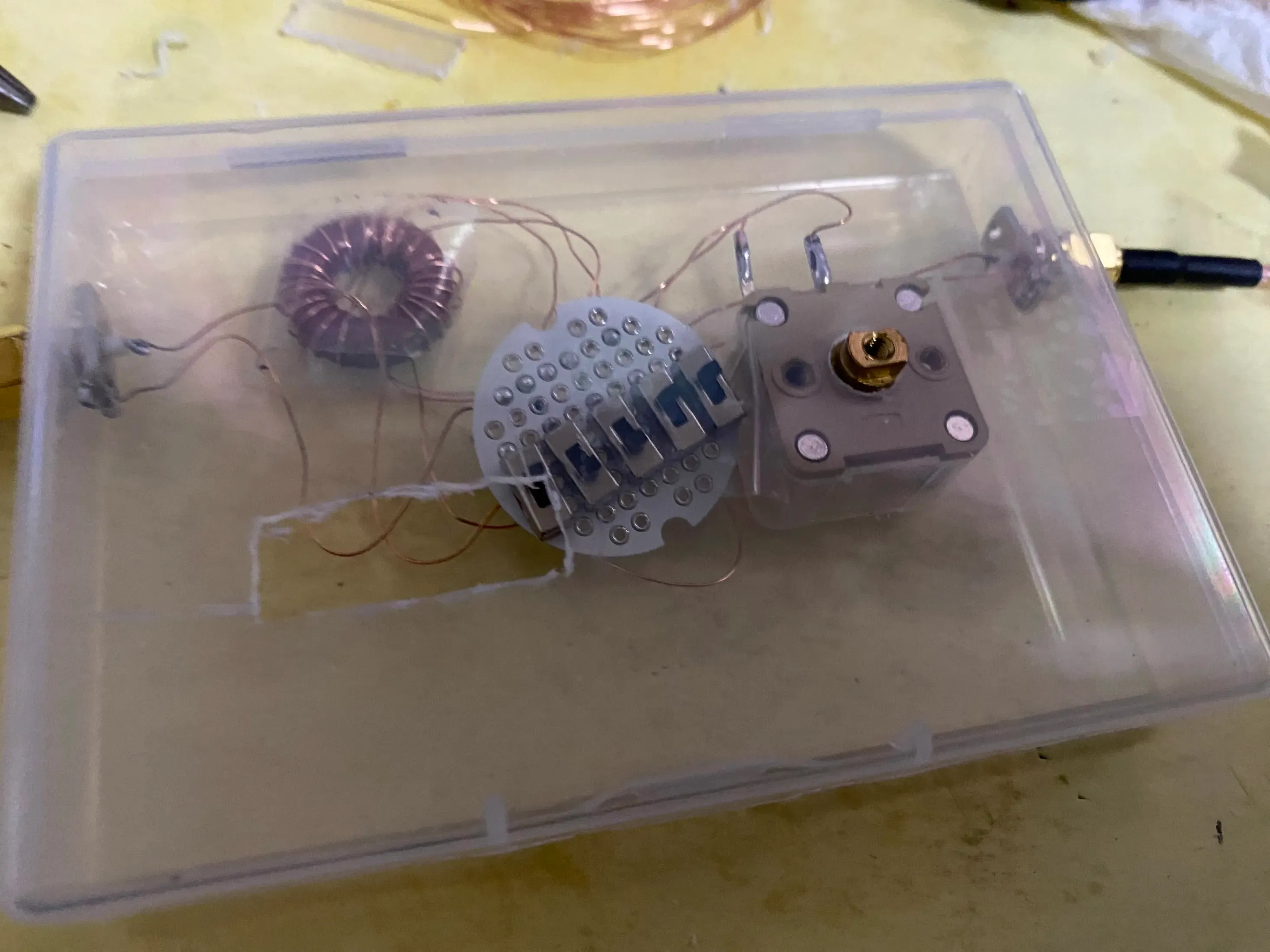
The toroid core, the board with the capacitors and switch, and the variable capacitor are laid out inside the case.
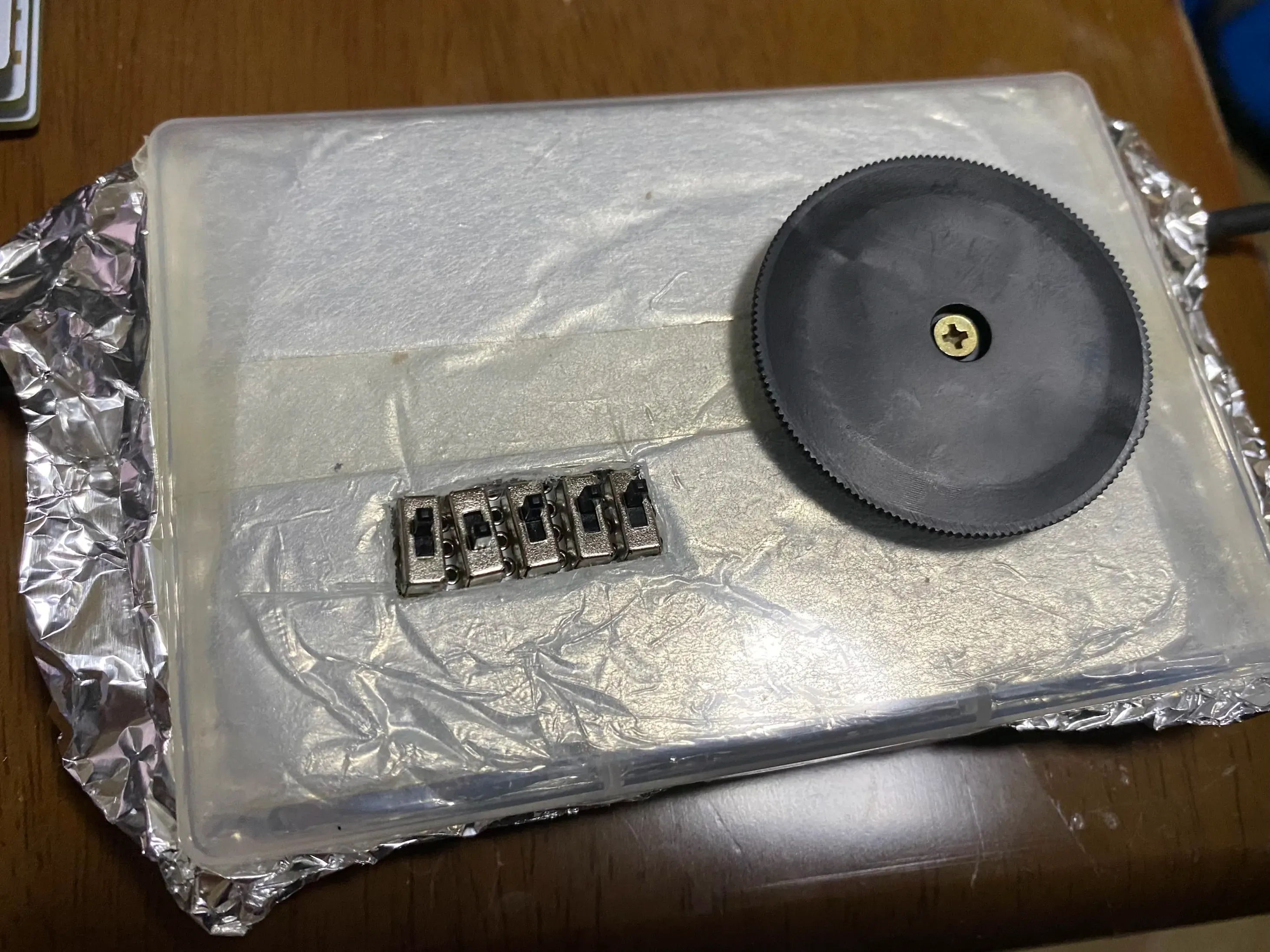
To keep outside noise from getting in, I lined the inside of the case with aluminum foil and connected it to the common ground. Solder won’t stick to aluminum foil, so I used a thick copper wire I’d salvaged earlier from taking apart a 100V lamp as the common ground, then wrapped part of it with the foil and crimped it down with pliers to ensure continuity.
(Note to future me: some of the copper wires are quite short, so if you try to open the case more than about 80 degrees, the wire may snap.)
While I was at it, I also hit “buy” on a NanoVNA.
Testing
I connected the finished preselector to the NanoVNA to check that it works. First, the transmission characteristic S21.
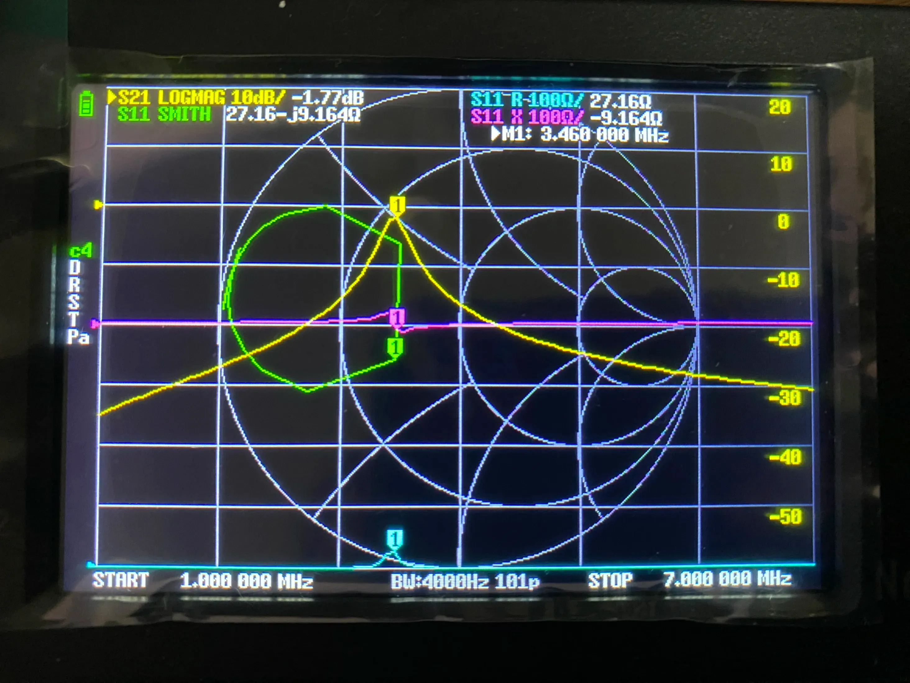
It really does draw a hill where S21 LOGMAG (the amount of signal loss) is around -2dB only at a specific frequency, and drops off sharply everywhere else. Amazing.
Next, I inserted the preselector between the antenna and the NanoVNA to check the SWR.
When I adjusted the variable capacitor, I could get the SWR down to a minimum of about 1.25 right at the frequency I wanted to listen to.
Then I put the preselector between the antenna and the RTL-SDR for real and checked the reception performance.
Adjusting the variable capacitor, the hump in the noise floor moves around beautifully. On the 7MHz band the skirts are a bit too wide for my liking, but if I move the peak to around 6.7MHz where there are no AM broadcasts, I can now raise the RF gain by about 10dB more than before without any intermodulation appearing.
Thoughts
Honestly I was half skeptical. I figured that even if it works in theory, it wouldn’t necessarily work in practice, but the results far exceeded my expectations. I never thought the LC resonant circuit stuff from my high school physics textbook would turn out to be this useful.
It’s a science backed by theory, so of course it works, but the world of high frequencies has an overall “The Black Magic” vibe, so I really didn’t expect it to actually succeed.
Bonus: Rethinking the Physical Layout of the Antenna
The previous setup was extremely simple: “about 20m random wire antenna -> 9:1 unun -> RTL-SDR”. In fact, before building the preselector, I started by improving the antenna itself, the cornerstone of the input. But that antenna improvement made the intermodulation problem even more serious, which is how I ended up building the preselector.
Capacitive Coupling with the Building (Steel Frame)
The exterior wall of the building and the antenna wire run in parallel only 1m apart. I thought I’d already improved things, since it used to be about 30cm, but from the point of view of long-wavelength HF radio waves, a 1m gap is practically zero distance.
The antenna and the steel frame inside the wall form a capacitor (capacitive coupling), and the faint high-frequency energy the wire worked so hard to pick up gets sucked away into the building’s ground.
The farther you move it from the wall, the smaller the coupling capacitance becomes.
By sticking a longer pole out from the balcony at about a 45-degree angle, I managed to isolate the wire to about 3m from the exterior wall. Reception sensitivity improved dramatically as a result, so next I had to build a BPF to get rid of the unwanted signals, which brings us to the start of this article.
More articles
- I Bought a Cheap Wideband LNA from AliExpress, the Zeenko ZK06-BM• #RadioI used the Zeenko ZK06-BM to intercept METEOR-M2 4 and got the best satellite image I've ever received.
- NOAA-15, 18 and 19 Are Out of Service, and the 137 MHz Analog Weather Satellites Are Gone• #RadioElon Musk is a cancer on humanity.

- Receiving METEOR M2-4 Weather Satellite Images with an RTL-SDR and a Homemade Yagi Antenna• #RadioI took on satellite reception with a homemade antenna that cost 300 yen (about $2).

- Getting Started with SDR Using an RTL-SDR Blog V4 and a Random Wire Antenna• #RadioA record of trying shortwave listening with a stealthy random wire antenna dangling off my balcony, from setting up the RTL-SDR Blog V4 to the before-and-after sensitivity gains of a homemade 9:1 unun.


Notes on games, radio and technology, translated from the Japanese blog.