Getting Started with SDR Using an RTL-SDR Blog V4 and a Random Wire Antenna

Table of Contents
Lately I’ve been hooked on my project to summon Noelle (the Genshin Impact character) into the real world with Home Assistant + ESP32.
Along the way, I wanted to control a device that needs to be operated with RF (radio) signals.
This is the record of how that led me down the SDR rabbit hole.
Off-the-Shelf Attempt (Failed)
First, I bought a smart remote that supports RF as well as IR (infrared).

↑ Not an affiliate link, don’t worry. Same goes for the rest of them.
Unfortunately, it couldn’t connect to the device I was after.
Getting Back into SDR
If that’s how it is, the only option left is to analyze the signal and transmit an identical one myself.
For the analysis, I first bought an RTL-SDR Blog V4.
Actually, I already own an RTL-SDR Blog V3, but it has vanished somewhere and I can’t find it. Since I bought it on Mercari (a Japanese flea market app), there was a chance it was a counterfeit anyway, so this time I went with Amazon, which I can trust.
Setup
I installed SDR++.


After installing the latest driver for the Blog V4, it started up without a hitch.


Just poking a piece of wire into the center pin of the antenna connector was enough to pick up FM radio around 90 MHz.
Let’s Build a Random Wire Antenna
The reason I lost interest back when I had the V3 was that I could hardly receive any signals. The 120 MHz airband was barely audible if I was lucky, and so was Chinese AM radio, and I almost never heard amateur radio operators chatting.
My total lack of knowledge about radio waves and high-frequency signals was what did me in, but maybe with AI’s help I can pull it off this time.
So I consulted Gemini 3 Pro Preview, and it suggested using a random wire antenna.
Now, I live on a low floor (single digits) of an apartment building in a city center. The view past my balcony is completely walled in by other buildings, and I can barely see the sky.
Apparently this is about the worst possible environment for receiving radio. Depending on the wavelength, a place with a poor line of sight makes it hard for signals to get in, and being surrounded by buildings means you pick up a ton of noise.
Even so, a random wire antenna might help, it said. Basically, you just let a long wire hang straight down under gravity and connect it to the center pin of the receiver.

Luckily, almost any wire will do. On the safety side, too, below my balcony is the roof of the ground-floor common area, so there are no power lines nearby and nobody walks there. I wanted to do this as stealthily as possible, so I went looking for a thin, long wire.
And then I found this at Daiso (a Japanese 100-yen store)!

A 0.28 mm x 30 m stainless steel wire. With this, the antenna wire dangling around would hardly be noticed, and it easily reaches all the way to the ground.
Stainless steel has higher electrical resistance than copper (meaning more signal loss), but for receive-only use it’s at a practically acceptable level. Apparently heating becomes an issue when transmitting, but I’m only receiving, and I can also expect it to resist rust and be strong. And above all, it’s super stealthy, which makes it perfect for just giving this a try.
I tied a washer to the end of the wire as a weight and quietly lowered it off the balcony in the middle of the night.
By the way, if you unwind the whole wire at once, it gets tangled into a horrible mess, so it’s best to pay it out little by little. (Learned that the hard way.)
After that, I made some tweaks like keeping it away from the wall, and the sensitivity improved dramatically. Not only Chinese AM radio, but even the voices of amateur radio operators on the 7 MHz band started coming in. Picking up a signal from Australia was seriously moving.
Let’s Build a 9:1 Unun
When I asked for advice on boosting sensitivity even further, I was told that the next step is to build a 9:1 unun.
An unun is an “unbalanced-to-unbalanced impedance transformer.” Put between the random wire antenna and the SDR to do impedance matching, it apparently brings a dramatic improvement in sensitivity.
Impedance is something I’ve never really understood since high school physics… so I took the opportunity to study it properly.
And then I found this wonderful video.
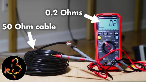
Indeed, if you think of impedance as “the resistance the electrons are expecting to run into”, everything clicks.
If you prepare exactly the resistance they were expecting, the electron traffic jam clears up smoothly, but if you betray their expectations, the electrons end up stopping and starting over and over. In terms of voltage, that’s what shows up as reflected waves in the circuit.
(Is that how it works?)
The problem with a random wire antenna is that its impedance is generally high, ending up at hundreds to thousands of ohms. The impedance used in radio, and assumed by SDR dongles, is 50 Ω, so a large signal loss happens right there.
That’s where the 9:1 unun comes in. Placed in between, it divides the antenna’s basically-too-large impedance by 9, bringing it closer to 50 Ω.
I don’t really understand the principle, but anyway, I went and bought a toroidal core and enameled wire.

Apparently, you twist three strands of enameled wire together (trifilar winding), pass them through the toroidal core about 7 turns, and connect it appropriately between the antenna and the SDR dongle.

Here, you have to be careful not to lose track of which wire at one end corresponds to which wire at the other. I stuck on tags made from Scotch tape and tissue paper.
…but after I cut off the leftover wire later, I lost track of them anyway. My multimeter was broken too, so I had no choice but to put myself in the circuit and run a high voltage through it, doing a human continuity check.
Anyway, I hooked it up. On Gemini’s advice, I connected a wire running along the indoor floor to the ground side as a counterpoise.

Here’s the wiring diagram, drawn up neatly.

With this, the noise floor around the 10 MHz band did indeed drop dramatically.
Before:

After:

On the other hand, around 7 MHz the noise actually got worse…?
Before:

After:

In terms of signal-to-noise ratio it looks like a slight improvement, so it might count as a success, more or less.
At the very least, 120 MHz and 433 MHz have turned into a -100 dB desert.
I think this is because the ferrite-core unun works for the HF band, and acts as a low-pass filter against higher frequencies like VHF/UHF, so signals no longer get through. When I analyze the smart remote, I’ll need to switch over to a different antenna.
Future Work
Do the Wiring Properly
Right now, I’m just bending the wires and hooking them together to connect them, but that falls apart if I so much as touch it, and I suspect it also adds weird resistance electrically, which isn’t good.
I’d like to make a sturdy, proper connection using crimp terminals, an acrylic box, and so on.
Move the Antenna Wire Even Farther from the Wall
The stainless wire was originally placed just a few centimeters from the wall. But when I stuck a tension rod out from the balcony to open up a gap of about 30 cm, the sensitivity improved dramatically.
So if I move it even farther away than 30 cm, I might be able to cut down on unwanted interference with the antenna’s characteristics and the noise coming from the household, and get an even better signal-to-noise ratio.
More articles
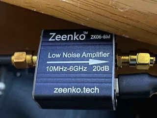
- I Bought a Cheap Wideband LNA from AliExpress, the Zeenko ZK06-BM• #RadioI used the Zeenko ZK06-BM to intercept METEOR-M2 4 and got the best satellite image I've ever received.
- NOAA-15, 18 and 19 Are Out of Service, and the 137 MHz Analog Weather Satellites Are Gone• #RadioElon Musk is a cancer on humanity.

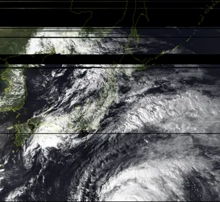
- Receiving METEOR M2-4 Weather Satellite Images with an RTL-SDR and a Homemade Yagi Antenna• #RadioI took on satellite reception with a homemade antenna that cost 300 yen (about $2).
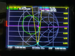
- Building a Homemade Preselector to Improve RTL-SDR Reception• #RadioI've finally started doing some actual radio-engineering electronics projects.

Notes on games, radio and technology, translated from the Japanese blog.